数据结构
首先观察一个简单的电路:
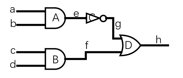
不难发现,根据信号的传导方向,可以将其转换成一个有向图:
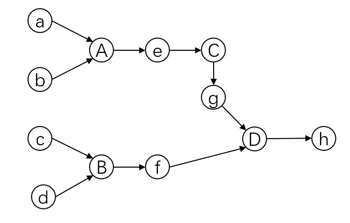
其中小写字母的顶点表示导线的结点,拥有电平状态,大写字母表示逻辑门,拥有逻辑运算的功能。
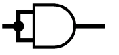
注意导线结点不能只作为边,因为可能会有多个逻辑门的端口连在一起,比如:
这个有向图里面存在几个特点,一是导线结点不允许接受多个输入,二是任意一条路径里面,导线结点和逻辑门一定会交替出现。
另外这个图里面有可能出现环,比如SR锁存器:
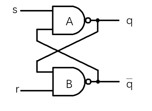
对应的图里面就存在环路:
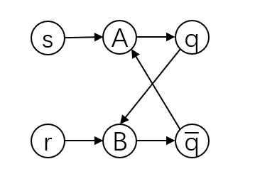
确定好了是个有向图就好办了,可以用邻接表来表示。
这里采用Java实现。
首先对于总的电路来说,需要记录所有的导线和逻辑门,虽然是在同一个图上,但为了方便,将导线结点和逻辑门分别存储在哈希表中,并且每个结点都拥有唯一的一个id:
1
2
3
4
5
6
|
class Circuit{
    HashMap<Integer, Node> nodeTable = new HashMap<>();
    HashMap<Integer, Gate> gateTable = new HashMap<>();
    ...
}
|
对于导线结点,需要记录一下相邻的所有逻辑门ID,然后用一个变量表示当前电平状态。
1
2
3
4
|
class Node{
    Set<Integer> gateIDs = new HashSet<>();
    boolean state;
}
|
对于逻辑门,需要分别记录输入和输出结点的ID,以及一个求值器:
1
2
3
4
5
6
|
class Gate{
    int[] inputNodeIDs;
    int[] outputNodeIDs;
    Evaluator evaluator;
    ...
}
|
另外就是输出端和输入端需要处理,这里把输入端当成只有一个输出口的特殊逻辑门,输出端当成只有一个输入口的特殊逻辑门。输入端具有一个状态,输出端具有一个listener,用来在状态更新的时候回调。
 1
 2
 3
 4
 5
 6
 7
 8
 9
10
11
12
|
class InputGate extends Gate {
    boolean state;
    ...
}
interface OutputListener{
    void OnUpdate(boolean state);
}

class OutputGate extends Gate {
    OutputListener listener;
    ...
}
|
连接
然后对Circuit类进行完善,虽然电路内部用node表示了连接状态,但是为了简化对外接口,只提供逻辑门的添加、删除和连接函数,导线结点node由Circuit内部维护,并且所有的逻辑门都通过ID进行索引,如:
 1
 2
 3
 4
 5
 6
 7
 8
 9
10
11
|
class Circuit {
    ...
    int addGate(OperType type) {...}
    int addInputGate(){...}
    int addOutputGate(){...}
    void setInputState(int id, boolean state){...}
    void setOutputListener(int id, OutputListener listener){...}
    void removeGate(int id) {...}
    void connectGate(int src_gate_id, int src_out_pin, int dst_gate_id, int dst_in_pin) {...}
    ...
}
|
通过这一系列的函数,可以任意构造逻辑电路,比如最开始的电路构造代码如下:
 1
 2
 3
 4
 5
 6
 7
 8
 9
10
11
12
13
14
15
16
17
18
|
        Circuit circuit = new Circuit();
        int a = circuit.addInputGate();
        int b = circuit.addInputGate();
        int c = circuit.addInputGate();
        int d = circuit.addInputGate();
        int A = circuit.addGate(OperType.And);
        int B = circuit.addGate(OperType.And);
        int C = circuit.addGate(OperType.Not);
        int D = circuit.addGate(OperType.Or);
        int h = circuit.addOutputGate();
        circuit.connectGate(a, 0, A, 0);
        circuit.connectGate(b, 0, A, 1);
        circuit.connectGate(c, 0, B, 0);
        circuit.connectGate(d, 0, B, 1);
        circuit.connectGate(A, 0, C, 0);
        circuit.connectGate(C, 0, D, 0);
        circuit.connectGate(B, 0, D, 1);
        circuit.connectGate(D, 0, h, 0);
|
将所有的逻辑门和结点输出成graphvz源文件,可以很方便查看连接状态:
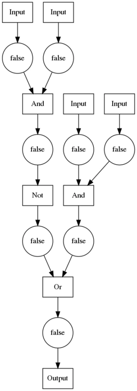
求值
电路仿真的核心在于如何求值,最简单的方法是把输入结点加入队列,然后用广度优先的方法依次求值,但这会涉及到大量的运算,即使是一个输入的改变也会导致与之相关的所有逻辑门重新求值,比如一个与门,输入状态从01变成00,即使这个逻辑门的输出没变,也会导致大量电路的重新求值,其次对于有环的电路也不好处理。一种更好的方法是基于事件驱动的方法,只在当结点状态发生改变的时候对与之相关的逻辑门进行求值,并且只有当这些逻辑门的输出发生改变的时候,才产生新的事件继续下去,直到所有的事件都被处理完成。
由于数据结构的设计上面,每个结点都保存了状态,因此事件产生的检测就较为容易了,只需要检测逻辑门的输出与对应的结点状态是不是一致即可。注意这里把输入端口也当作一个逻辑门,因此可以统一对待。
具体实现来说,需要维护两个队列,一个逻辑门队列gateQueue,保存待求值的逻辑门,一个结点队列nodeQueue,用来标记状态发生改变的结点。这样一来,算法就很简单了:
1
2
3
4
|
1.把所有已改变的输入端加入gateQueue
2.从gateQueue取出所有gate进行求值,当求值的结果与输出端的node状态不一致时,更新node的状态,并将其加入nodeQueue
3.当nodeQueue为空时,结束,否则将输入口与之想连的gate加入gateQueue(已有就不加)
4.重复2、3步骤
|
添加逻辑门以及设置输入状态的时候把逻辑门加入gateQueue,删除逻辑门的时候从gateQueue中删除,然后进行求值,清空gateQueue,这样就能维护好一个电路的状态了。
具体的代码实现来说,使用LinkedHashSet来存nodeQueue和gateQueue,如:
 1
 2
 3
 4
 5
 6
 7
 8
 9
10
11
12
13
14
15
16
17
18
19
20
|
    void process() {
        while (!gateQueue.isEmpty()) {
            LinkedHashSet<Integer> nodeQueue = new LinkedHashSet<>();
            for (int gid : gateQueue) {
                Gate gate = gateTable.get(gid);
                Set<Integer> changed = gate.Evaluate(nodeTable);
                nodeQueue.addAll(changed);
            }
            gateQueue.clear();
            for (int nid : nodeQueue) {
                Node node = nodeTable.get(nid);
                for (int gid : node.gateIDs) {
                    Gate gate = gateTable.get(gid);
                    if (gate.hasInput(nid))
                        gateQueue.add(gid);
                }
            }
            nodeQueue.clear();
        }
    }
|
测试
把电路中的c输入口置为1,然后求值,结果如下:
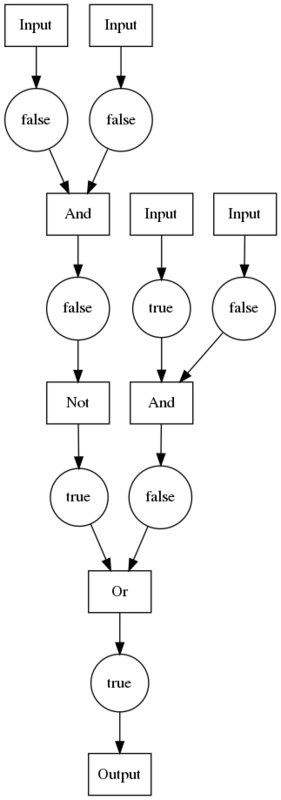
可以看到已经得到了正确的结果。
构造一个sr latch:
 1
 2
 3
 4
 5
 6
 7
 8
 9
10
11
12
13
14
15
16
17
18
19
20
|
        int A = circuit.addGate(OperType.AndNot);
        int B = circuit.addGate(OperType.AndNot);
        int s = circuit.addInputGate();
        int r = circuit.addInputGate();
        int q = circuit.addOutputGate();
        int qbar = circuit.addOutputGate();
        final boolean[] result = new boolean[2];
        circuit.setOutputListener(q, (state) -> {
            result[0] = state;
        });
        circuit.setOutputListener(qbar, (state) -> {
            result[1] = state;
        });

        circuit.connectGate(s, 0, A, 0);
        circuit.connectGate(r, 0, B, 1);
        circuit.connectGate(A, 0, q, 0);
        circuit.connectGate(B, 0, qbar, 0);
        circuit.connectGate(B, 0, A, 1);
        circuit.connectGate(A, 0, B, 0);
|
连接图如下:
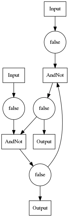
然后分别用01,11,10测试,01应该对qbar置位,11应该保持,10应该对q置位:
 1
 2
 3
 4
 5
 6
 7
 8
 9
10
11
|
        circuit.setInputState(s, true);
        circuit.process();
        System.out.println(Arrays.toString(result));

        circuit.setInputState(r, true);
        circuit.process();
        System.out.println(Arrays.toString(result));

        circuit.setInputState(s, false);
        circuit.process();
        System.out.println(Arrays.toString(result));
|
结果为:
1
2
3
|
[false, true]
[false, true]
[true, false]
|
符合预期。